The Chamber
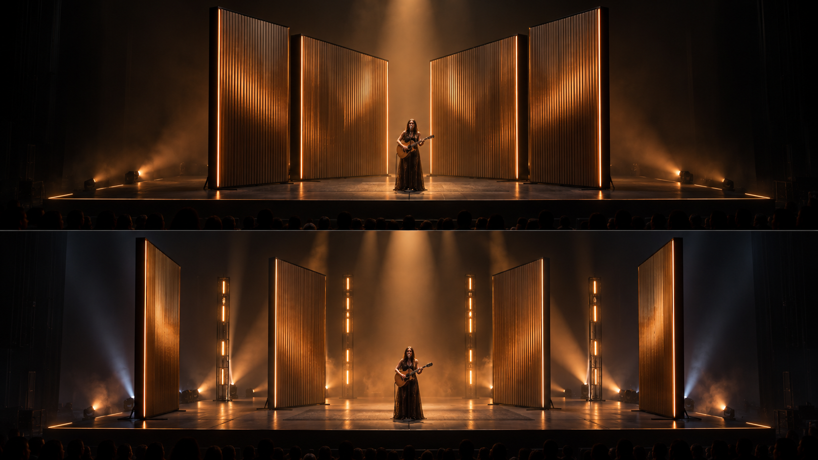
Panels turn inward to compose a compact backdrop. Concentrated light and angled surfaces frame the performer.
A performance environment that transforms physically in real time, making the stage itself an active participant in the show.
Live entertainment · Mechanical engineering · Scenic design · Show control
What if a stage could change its physical identity as dramatically as the music changes its emotional character? The Living Stage explores a modular performance environment whose moving scenery changes enclosure, sightlines, and the reveal of light throughout a show.
This first configuration narrows the broader brief to one reproducible motion: four floor-mounted scenic panels rotate around fixed vertical pivots. Mirrored pairs create an intimate chamber, then open to expose fixed lighting columns. The deck and lighting positions stay fixed; the panel faces do the transforming.
Panels turn inward to compose a compact backdrop. Concentrated light and angled surfaces frame the performer.
Paired panels slowly pivot outward. Gaps emerge, revealing the mechanism's spatial rhythm and hidden lighting.
Panels reach their open positions. More of the fixed lighting architecture becomes visible and the stage reads at its widest scale.
Panels return through a different cue sequence. A staggered composition restores intimacy without simply replaying the opening.
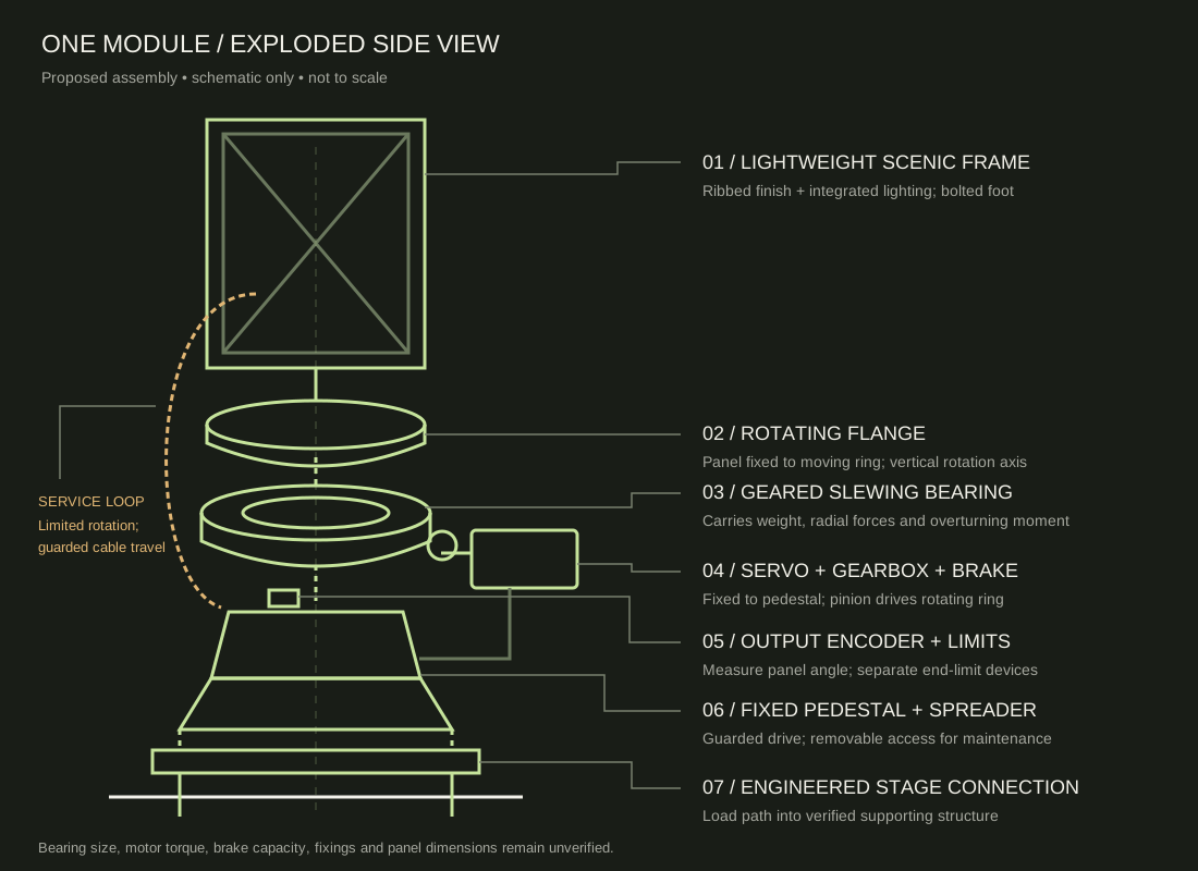
Each lightweight panel bolts to a rotating flange carried by a geared slewing bearing. The fixed bearing ring mounts to a pedestal and spreader frame connected to the supporting stage structure. The intended load path is panel → flange → bearing → pedestal → spreader → verified stage connection.
A pedestal-mounted servomotor and gearbox drive a pinion against the rotating ring. An output encoder measures panel angle rather than relying only on motor rotation. A holding brake, separate end-limit devices, engineered mechanical stops, and guarded drive access form part of the proposed assembly.
The proposed visual study uses approximately 75° of panel travel from the chamber pose. Mirrored pairs turn in opposite directions. A guarded flexible service loop carries power and data to the panel lighting over that limited arc; continuous rotation is outside this configuration.
Panel height, width, mass, inertia, movement speed, stopping distance, bearing capacity, drive torque, anchorage, and stage loading remain design inputs to resolve. The system has no overhead moving scenery or performer lifting in this initial study.
Move the control to compare the chamber and expansion poses. This plan view illustrates fixed pivots, mirrored rotation, and a separate central performance area. It is a geometric concept study, not a collision or safety simulation.
A show-control cue requests a validated position sequence. The motion controller executes the travel profile and checks position feedback. Lighting follows cue timing through its own controller. Operators authorize movement with the scenic travel area clear.
A dedicated safety control path handles emergency stops, interlocks, drive enable, and the engineered stopping response. The holding brake is not assumed to be an emergency stopping brake. A fault stops the sequence and requires operator inspection and deliberate reset; show control cannot bypass the protective system.
Cue list, operator command, intended panel positions, synchronized lighting cues.
Drive profiles, output encoders, position confirmation, travel limits, fault status returned to the operator.
Separate protective path to drive enable and stopping functions. Required architecture follows risk assessment.
The modules would separate into panel frames, pivot pedestals, and spreader sections for transport. Repeatable connections, protected cabling, access to drive components, and defined assembly checks would support load-in, maintenance, and strike.
| Phase | Proposed deliverable |
|---|---|
| Concept design | Four scenic states, sightlines, motion sequence, spatial envelope. |
| Engineering | CAD assemblies; load paths, bearing and drive sizing; support structure and risk assessment. |
| Prototype | Reduced-scale moving module to test geometry, control logic, and cable routing. |
| Fabrication | Full-scale module with representative panel mass and final connection strategy. |
| Integration | Drives, position feedback, lighting, guards, interlocks, and safety functions. |
| Commissioning | Load and motion tests, stopping performance, cue validation, operator training. |
| Deployment | Transport, venue survey, assembly verification, rehearsals, show operation, strike. |
Transportability, venue compatibility, structural and operational safety, repeatable motion, and efficient installation shape the design from the beginning. A smaller venue could use fewer modules, subject to a revised geometry and cue review.
Mechanical engineering can become a creative medium. This study brings scenic design, fabrication, show control, and production planning together to explore how physical transformation contributes to live storytelling.
Independent technical and creative concept study. The environment has not been built. Images are AI-generated concept renders; diagrams describe a proposed mechanism. No engineering calculations, prototype results, selected equipment, or certified safety design are represented. Qualified structural, mechanical, controls, and entertainment safety review would be required before fabrication or operation.
Technical reference: igus — slewing bearing principles. This supports the general bearing load-path approach; it does not validate this proposed assembly or select a product.